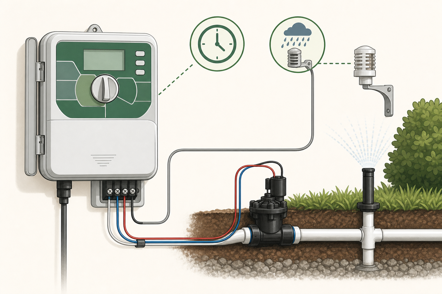
A basic timer and a smart controller can both automate irrigation. The right choice depends on the number of zones, water-use variability, need for remote control, sensor compatibility, and how much maintenance you are willing to perform.
Choose a basic timer when
You have one or a few simple zones.
The schedule changes only seasonally.
Reliable local control matters more than phone access.
Wi-Fi coverage is poor or account-based services are undesirable.
You are prepared to use rain delay and adjust runtimes manually.
Choose a smart controller when
You manage several zones with different plant or soil needs.
Remote start, stop, alerts, and schedule changes solve a real problem.
Weather-based adjustment can reduce frequent manual changes.
You want flow monitoring or integration with compatible sensors.
The installation has reliable power, Wi-Fi, and ongoing support.
What “smart” does not fix
A controller cannot correct undersized tubing, a clogged filter, poor pressure, broken valves, mixed sprinkler precipitation rates, or emitters placed in the wrong root area. Stabilize the hydraulic system before upgrading controls.
Compare these specifications
Number of supported zones and expansion options
Indoor or outdoor enclosure rating
Electrical compatibility with valves and master valve or pump relay
Rain, freeze, soil-moisture, and flow-sensor support
Manual operation when internet service is unavailable
Subscription requirements and long-term app support
Weather data source and local watering-restriction features
A low-risk upgrade path
Start with a reliable schedule, measure emitter or sprinkler output, and use a rain delay. Upgrade when remote access or automatic adjustment will save enough time or water to justify added setup and dependence on connectivity.
For a small faucet-fed drip zone, a quality battery timer may be the better tool. For multiple landscape zones with changing conditions, a compatible smart controller can provide useful control and visibility.
Affiliate disclosure: This page contains an affiliate link. If you purchase through it, DripResolve may earn a commission at no extra cost to you. Our editorial assessment remains independent.
A rain sensor that does not stop scheduled watering may be dry, bypassed, incorrectly wired, incompatible with the controller, poorly located, or defective. Smart weather adjustment and a physical rain shutoff sensor are also different features.
Confirm enough rain reached the sensor
The sensor must be exposed to rainfall but not direct sprinkler spray. Roof overhangs, dense foliage, and gutters can keep it dry. Many cork-disc sensors require enough rainfall to swell the discs before they open the control circuit.
Check controller status
Set the sensor switch to Active rather than Bypass.
Confirm the relevant program or stations are not configured to ignore the sensor.
Look for sensor, rain-delay, or communication indicators.
For a wireless model, check battery and receiver status.
Test the sensor safely
Follow the manufacturer’s manual. Many mechanical sensors have a test spindle: while a manual cycle is running, pressing it should stop irrigation. If the controller responds, wiring and logic may be working and the problem may be exposure or adjustment.
Inspect wiring and jumpers
A factory jumper usually occupies the sensor terminals when no sensor is installed. It generally must be removed when a compatible normally closed sensor is connected. Loose splices, staples through insulation, corrosion, and wrong terminal placement can keep the circuit from changing state.
Smart controller confusion
Weather-based seasonal adjustment may change future runtime without cancelling a schedule immediately after rain. Use the controller’s rain delay or compatible physical sensor if immediate shutoff is required.
When replacement is reasonable
If location, settings, wiring, battery, compatibility, and the manual test are all correct but the circuit never changes, the sensor or receiver may have failed. Match the replacement’s contact type and compatibility to the controller.
Turn off controller power before changing wiring and follow local electrical rules.
If an irrigation timer will not start watering, separate a scheduling problem from a power, sensor, wiring, valve, or water-supply fault. Start with non-invasive checks before opening electrical equipment.
Does the display work?
A blank display suggests depleted batteries, a disconnected transformer, a tripped outlet or breaker, or an internal power fault. Replace batteries with the specified type and test the outlet with an appropriate device. Mains-voltage work belongs to a qualified professional.
Try a manual start
If manual watering works, the field wiring and valve may be functional and the problem is likely in the schedule. If manual watering also fails, check the water supply, sensor status, controller output, wiring, solenoid, and valve.
Check the complete program
Correct current time, date, and AM/PM setting
At least one active watering day
A valid program start time
A non-zero runtime for the station
Controller set to Run or Auto
No active rain delay, seasonal adjustment at zero, or programmable-off period
One start time normally launches all programmed stations in sequence. Adding a start time for every station can cause repeated watering rather than fixing a missed schedule.
Inspect the sensor circuit
A wet rain sensor, bypass setting, loose sensor wire, or missing jumper on an unused sensor terminal can prevent operation on some controllers. Follow the exact wiring diagram for the model.
If the controller runs but no water flows
Confirm the main and zone supplies are open. A station error may indicate shorted field wiring or a failed solenoid. If the valve opens manually but not electrically, focus on the controller output, common wire, station wire, and solenoid.
Turn off electrical power before touching wiring. Do not apply voltage to terminals unless the manufacturer’s procedure calls for testing and you have the appropriate experience and meter.
There is no universal emitter count. The safe number depends on the flow of each emitter, available source flow, tubing diameter, line length, elevation, and the manufacturer’s maximum lateral length.
Calculate total zone flow
Add the rated flow of every emitter. Twenty 1-gallon-per-hour emitters require 20 gallons per hour. Mixed emitters must be calculated separately and then added together.
Total flow = number of emitters × flow per emitter
Compare the whole flow path
The total must fit within the capacity of the source, timer or valve, filter, pressure regulator, mainline, and lateral tubing. The smallest-capacity component limits the zone.
Why line length matters
Pressure is gradually lost as water moves through tubing. Small tubing, long runs, high flow, fittings, and uphill sections increase the loss. A line may have enough total source flow but still deliver too little at its far end.
Use a practical field check
Confirm the tubing and emitter specifications.
Calculate total emitter demand.
Run the completed zone at normal pressure.
Collect water for the same amount of time from representative emitters near the beginning and end.
If output differs materially, shorten the lateral, reduce demand, increase the supply-line size, or divide the zone.
Do not use 1/4-inch tube as a long mainline
Small feeder tubing is best for short branches to individual plants or emitters. Use the larger distribution tubing recommended by the system manufacturer for long runs.
Plants determine spacing
Emitter count is not only a hydraulic question. Soil texture, root area, plant size, emitter flow, and the percentage of soil that must be wetted determine how many emitters each plant needs. As trees and shrubs grow, move or add emitters near the expanding root zone while keeping the zone within capacity.
When specifications are unavailable, divide the system into conservative zones and test uniformity rather than relying on a generic maximum count.
A drip fitting should stay dry while the zone is running. A slow drip or spray at a connector usually means the tubing and fitting do not match, the tube is damaged, the connection is incomplete, or pressure is too high.
Find the exact leak
Dry the area, run the zone, and watch where water first appears. Water can travel along tubing and make a sound connection look guilty.
Common causes
The tubing outside diameter does not match the fitting.
The tube was not pushed fully over the barb or into the compression fitting.
The end is oval, stretched, split, or cut at an angle.
A clamp is missing where the manufacturer requires one.
The zone has no regulator or the regulator rating is too high.
The fitting has been reused after its grip was damaged.
Repair the connection
Shut off the water and release pressure.
Cut the damaged tubing back to clean, round material with a square cut.
Confirm the actual tubing size and use a compatible fitting.
Warm stiff polyethylene tubing in warm water if the manufacturer permits it; do not use an open flame.
Reconnect fully and test at normal operating pressure.
Barbed versus compression fittings
Both can work well when correctly sized. Barbed fittings depend on an interference fit and may require a clamp. Compression fittings grip the outside of the tube and are particularly sensitive to outside diameter. Nominal labels such as “1/2 inch” are not always interchangeable between brands.
If several connections leak
Measure operating pressure and inspect the regulator before replacing every fitting. Repeated failures across the zone point to overpressure, incompatible tubing, heat-damaged material, or poor installation rather than several unrelated bad fittings.
Do not seal a mismatched connector with household glue or tape. Use irrigation-rated parts that match the tubing and pressure.
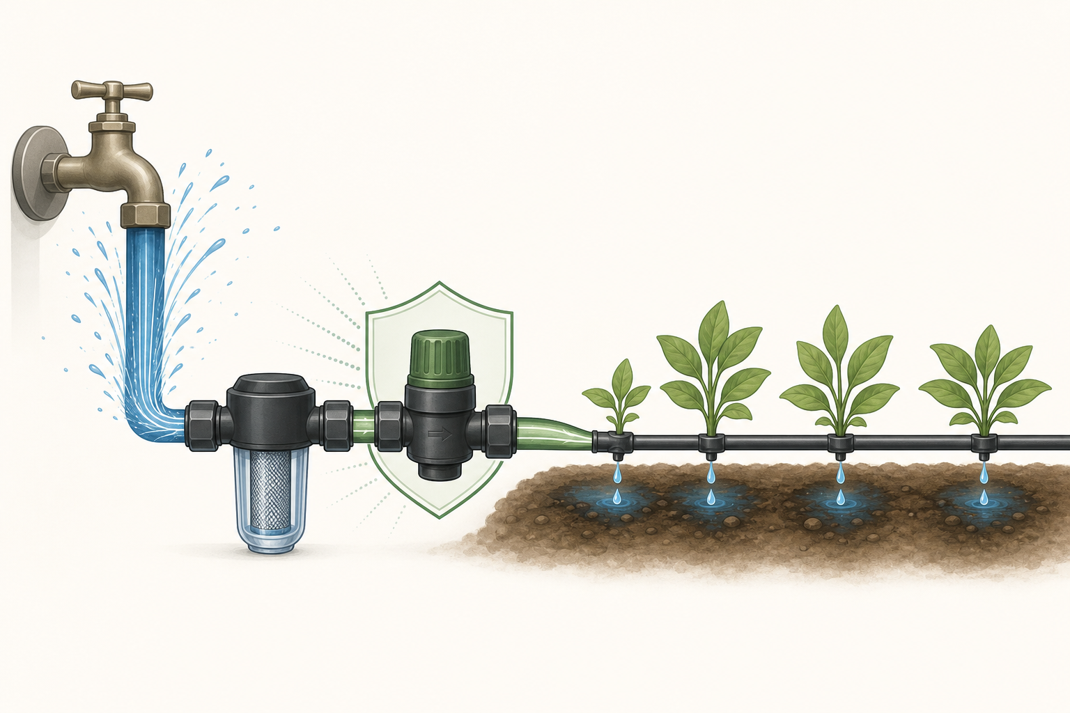
A small drip system can be automated without making it complicated. The goal is a reliable chain: safe water connection, filtration, pressure control, one correctly sized zone, and a timer that opens it for a measured duration.
Start with the hydraulic basics
Automation cannot fix a poorly balanced zone. Before adding a timer, repair leaks, clean the filter, flush the lines, and confirm that the first and last emitters deliver similar flow.
Core components
Backflow protection appropriate for the water connection and local rules
A battery hose timer or wired irrigation controller
A filter sized for the emitter requirement and total flow
A pressure regulator matched to the drip equipment
Main tubing, short feeder branches, emitters, and flushable end closures
Choose the simplest controller that meets the need
A basic battery timer is often enough for one faucet-fed zone. A multi-zone controller makes sense when plant groups need different schedules. Smart control is useful only if remote access, weather-based adjustment, alerts, or multiple zones solve a real problem.
Affiliate disclosure: This page contains an affiliate link. If you purchase through it, DripResolve may earn a commission at no extra cost to you. Our editorial assessment remains independent.
For a single faucet-fed zone that only needs scheduled on/off control, you can review the RainPoint automatic hose timer as one concrete example when comparing connection size, pressure limits, schedule range, and rain-delay features.
Build the zone around plant needs
Keep plants with similar water requirements on the same zone. Do not combine containers, established shrubs, and lawn sprinklers under one schedule. Count the total emitter flow and stay within the capacity of the source and every component.
Set a schedule by measurement
Do not copy a universal “minutes per day” setting. Place small containers under representative emitters, run the system for a known time, and compare output. Then adjust runtime and frequency for soil, weather, plant size, and season. Check soil moisture below the surface before increasing frequency.
Add intelligence only after reliability
A rain or soil-moisture sensor can prevent unnecessary watering, but it must be compatible with the controller and correctly located. Weather-based controllers need accurate site settings. Keep a manual shutoff accessible for leaks or maintenance.
Monthly maintenance
Run the zone while watching every branch.
Clean the filter and flush line ends.
Replace damaged or clogged emitters.
Move or add emitters as plants grow.
Update seasonal schedules instead of leaving one program all year.
The best automated system is not the one with the most features. It is the smallest system that delivers even water, stops reliably, and is easy to inspect.
Most faucet-fed drip systems need a pressure regulator when supply pressure exceeds the equipment’s recommended working pressure. For many garden emitter systems, 25 PSI is a useful starting point; drip tape often needs about 10–15 PSI. Choose the actual setting from your tubing and emitter specifications, then check that your zone’s flow matches the regulator.
The number on the regulator is only part of the decision. A correctly labeled regulator can still perform poorly if too little water passes through it or the inlet pressure is insufficient.
Do you need a pressure regulator for drip irrigation?
A regulator reduces excessive incoming pressure to a suitable downstream level. It helps protect drip components from leaks, separated connections and excessive emitter flow. DIG describes its 25 PSI regulator as a way to bring household supply pressure into the working range of its drip equipment. See DIG’s specifications and installation guidance.
You may already have suitable regulation in a drip-zone assembly. Check its outlet setting and flow range before adding another regulator. A timer alone does not establish that pressure regulation is included.
If the source already delivers stable pressure within every downstream component’s permitted range, a separate regulator may be unnecessary. Verify the pressure during operation. A regulator cannot boost a weak supply; for that problem, start with Why Is My Drip Irrigation Pressure So Low?
What PSI should you use: 10, 15, 25 or 30?
Start with the exact equipment, especially whether you have thin-wall drip tape or thicker dripline. These starting points are not interchangeable product ratings.
Your system
Pressure to investigate
What decides the setting
Thin-wall drip tape
Often 10–15 PSI
The tape’s wall thickness, operating range and maximum pressure
Garden tubing with separate drip emitters
Often 25 PSI
Emitter requirements and tubing/fitting limits
Landscape dripline
25 or 30 PSI may suit the design
The specific dripline’s pressure range and lateral-length tables
Pressure-compensating dripline
Use its specified design pressure
Compensation range, line length, elevation and component limits
Clemson Extension gives 30 PSI for typical landscape drip tubing and 10 PSI for garden drip tape. This explains why advice differs by system type; it does not make either number universal. Read Clemson’s filter and pressure-regulator guidance.
Some products allow a much wider operating range. For example, Rain Bird lists 8.5–60 PSI for XPC pressure-compensating dripline. That is an operating range for that product, not a recommendation to run an entire mixed-component garden system at 60 PSI. See the XPC technical sheet.
Pressure-compensating emitters do not replace system pressure protection. They stabilize emitter output within their specified range; tubing, fittings and other parts still have pressure limits.
Check flow rate before buying a regulator
Drip irrigation pressure regulators have a working flow range as well as a PSI rating. Calculate the demand of the zone that will actually run:
For example, 12 emitters rated at 1 GPH total 12 GPH, or 0.2 GPM. That is below the 0.5 GPM minimum listed for Senninger’s PRL regulators. A regulator from that range would therefore be outside its published flow specification for this example, even with the right outlet PSI. Check the PRL flow specifications.
Choose a model whose documented range includes your demand. For dripline, use its flow-per-length specification or calculate from emitter spacing. Include only outlets operating together. Our guide to how many drippers can go on one line explains the wider sizing checks.
Before ordering, record the required outlet PSI, minimum and maximum GPM, permitted inlet pressure and connection type. Hose threads and tapered pipe threads are different; matching the nominal diameter alone is not enough.
Where does the pressure regulator go?
For a typical separate-component drip-zone assembly, the working order is control valve or timer → filter → regulator → drip tubing. Position backflow protection according to the approved device’s instructions and the requirements for your water connection; there is no single placement diagram that fits every device.
DIG’s D46 instructions place the filter before the regulator and, for its illustrated automated faucet setup, the timer before the backflow device. Combined filter/regulator assemblies have their own instructions. Follow the manufacturer’s installation diagram.
Many basic irrigation regulators must be downstream of shutoff valves because they are not designed for continuous supply pressure. Do not put one before a timer unless its documentation explicitly permits that arrangement. DripWorks explains the constant-pressure limitation.
Shut off the water and release pressure before opening connections. Match the flow arrow to the direction of water travel, support the assembly and use the specified thread-sealing method. For the full watering setup, see how to automate a small drip irrigation system.
How to test a drip irrigation pressure regulator
Test while the zone is watering. A gauge attached to a closed outlet measures a no-flow condition, which may not show the regulated operating pressure.
With the water off and pressure released, fit suitable gauge connections upstream and downstream of the regulator. Use a tee or test port that leaves water flowing to the emitters.
Run the normal zone and allow the readings to stabilize.
Check inlet pressure against the regulator’s requirements and compare downstream pressure with its specified output and tolerance.
If the readings are suitable, compare water delivery near the beginning and end of the dripline.
Senninger’s catalog describes this two-gauge check and specifies at least 5 PSI above the outlet setting for the models covered. A 25 PSI model with that requirement needs at least 30 PSI at its inlet while operating. Check your own model’s required margin. See Senninger’s testing and sizing guidance.
Why is the pressure still wrong?
What you observe
Next check
Outlet pressure stays too high
Confirm the measurement is under flow, then check minimum flow, orientation and the model’s rating.
The whole zone runs weakly
Check inlet pressure under flow, the filter, valve opening and total demand before blaming the regulator.
Only the far end is weak
Check line length, restrictions, elevation and sizing; do not exceed component limits to compensate.
Connections keep leaking
Check operating pressure and fitting compatibility. A leak alone does not prove regulator failure.
If pressure is suitable but connections still leak, use the drip connector repair guide. Replace a suspect regulator only after checking supply conditions, flow range and installation.
Common questions
Can I just turn the faucet down?
A partly closed faucet restricts flow but does not maintain a preset downstream pressure as demand changes. Use an appropriately sized regulator when pressure reduction is needed. Clemson explains the limitations of using a valve this way.
Is 15 PSI enough for drip irrigation?
It can be, if the specific equipment operates correctly at that pressure throughout the zone. It is not automatically suitable for every dripline. Check minimum operating pressure and line-length guidance.
Does a gravity-fed system need a regulator?
Do not add a conventional regulator automatically to an already low-pressure supply. Verify available operating pressure and use equipment designed for those conditions. A regulator reduces pressure; it cannot create it.
Should each zone have its own regulator?
Size regulation for the zones and flows that operate together. Separate downstream regulators can accommodate different pressure requirements. A shared assembly needs to be suitable for its location and every intended operating combination.
Before buying: identify your drip equipment, calculate the active zone’s flow and measure running pressure. Those three checks give you a much stronger basis for choosing a regulator than the PSI label alone.
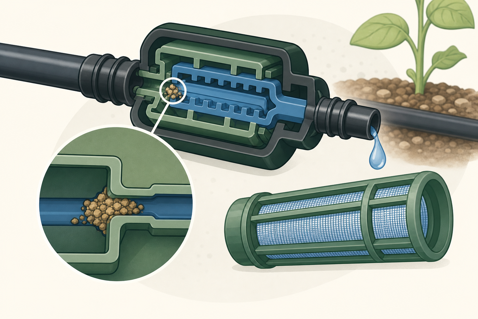
Recurring emitter clogs are a symptom of contamination in the water or deposits forming inside the system. Replacing one blocked emitter may restore flow today, but the clog will return until the source is controlled.
Three common types of clogging
Physical particles
Sand, soil, rust, and pipe debris can enter through the water source or during repairs. A correctly sized screen or disc filter is the main defense.
Biological growth
Algae, bacteria, and slime are more common with ponds, tanks, wells, or systems exposed to light and warm water. They can coat filters and small emitter passages.
Mineral deposits
Hard water can leave calcium or other precipitates. Iron in well water can also create deposits. The correct treatment depends on water chemistry; guessing with acids or chlorine can damage equipment or create a safety hazard.
What to do first
Inspect and clean the filter.
Open line ends and flush until the water is clear.
Check several emitters to see whether clogging affects one branch or the whole zone.
Replace emitters that cannot be restored without changing their opening.
Prevent the next clog
Use the filter mesh specified by the emitter manufacturer.
Choose a filter with enough flow capacity for the zone.
Keep end caps accessible and flush laterals periodically.
Prevent soil from being sucked into open emitters when the system drains.
Inspect filters more often when the source carries heavy sediment.
Should you clean an emitter?
Removable emitters can sometimes be rinsed according to their manufacturer’s instructions. Do not push a needle or drill bit into the outlet: it can permanently change the flow. With inexpensive sealed emitters, replacement is often more dependable.
When water testing makes sense
If mineral scale, orange deposits, slime, or rapid repeated clogging appears, test the source water and ask an irrigation professional or water-treatment specialist for a compatible treatment. Chemical injection requires correct equipment, backflow protection, dosing, and safety procedures.
A clean filter plus regular flushing prevents most household drip problems. Persistent clogs point to a water-quality issue or unsuitable filtration—not bad luck.
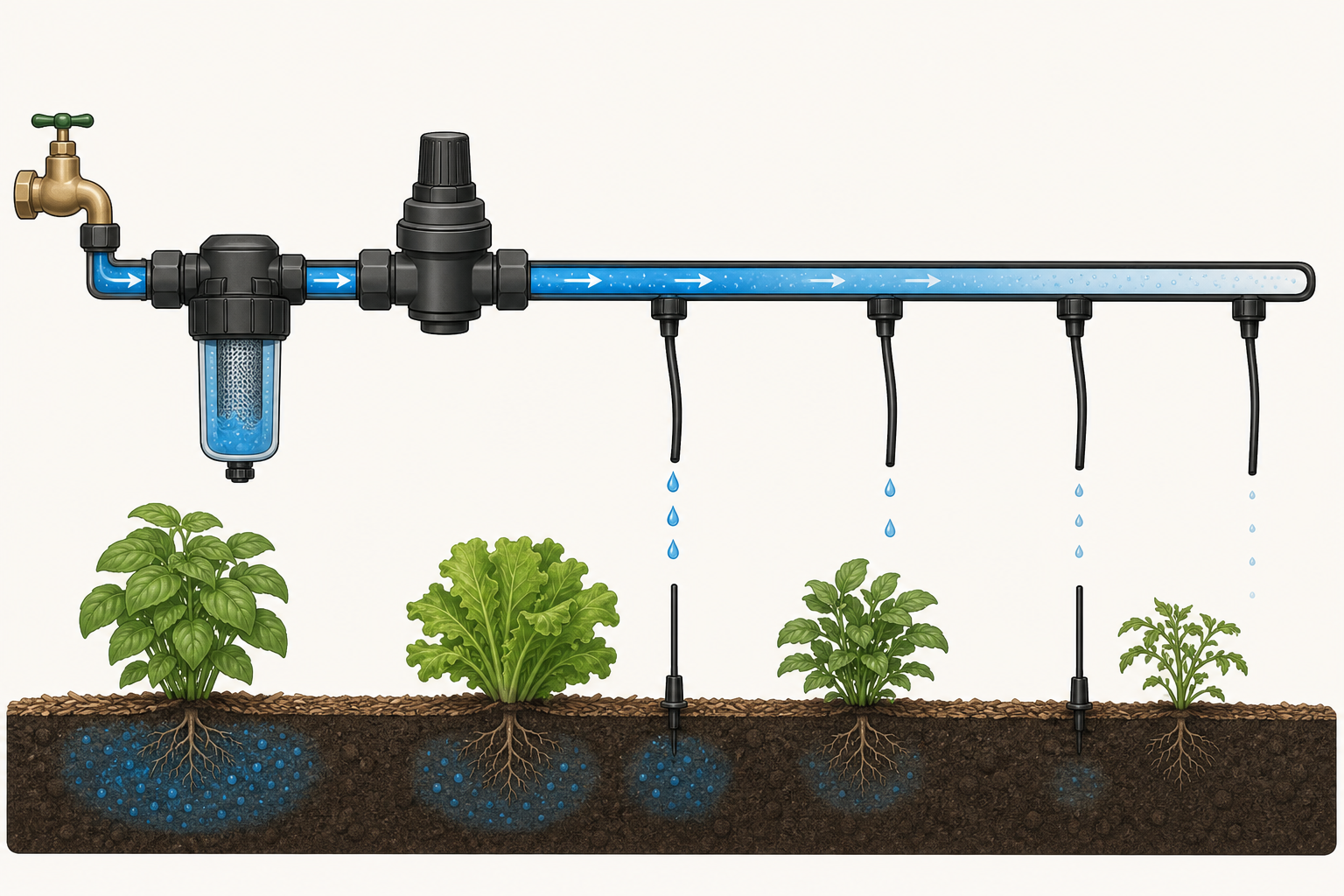
When the first emitters work but the last plants stay dry, the system is losing too much pressure or flow before water reaches the end. The cause is usually excessive line length, too many emitters, a restriction, a leak, or an elevation change.
Confirm the pattern
Run the zone and compare the first, middle, and last emitters. If flow fades gradually, suspect hydraulic limits. If it stops suddenly, inspect that point for a kink, plugged fitting, closed valve, or blocked section.
Flush the lateral
Turn off the water, remove the end cap, then briefly run the zone into a bucket or safe drainage area. Sediment often collects at the end of a lateral. Refit the cap after the water runs clear.
Check for hidden losses
Wet patches can indicate split tubing or a connector that has come loose.
Mulch or soil may hide a kink or crushed section.
A dirty filter can reduce flow to the entire zone.
Partially open valves and failing timers can restrict the supply.
Count the total flow
Add the rated flow of every emitter on the zone. The total must stay below what the water source, valve, regulator, filter, and tubing can supply together. Small 1/4-inch tubing should normally serve short branches, not act as the main supply for a long row.
Consider slope and line layout
Water pressure changes with elevation. On slopes or long runs, pressure-compensating emitters can improve uniformity, but they still need adequate inlet pressure. A looped layout or a larger supply line can also reduce differences between the start and end.
The most reliable fixes
Clean the filter and flush the line.
Repair leaks and straighten damaged tubing.
Reduce the number of emitters per lateral.
Feed long laterals from a larger mainline.
Split an oversized zone into two independently controlled zones.
Do not solve an end-of-line problem by increasing pressure beyond the tubing or emitter rating. Better distribution and correct zone sizing are safer and more reliable.
Low pressure in a drip irrigation system usually shows up as weak flow, dry plants at the far end of a line, or emitters that stop dripping when another zone opens. The fastest way to solve it is to find where pressure or flow is being lost instead of replacing parts at random.
Start with a quick diagnosis
Run only the affected drip zone.
Check whether every emitter is weak or only the last section.
Inspect the filter and pressure regulator.
Look for leaks, crushed tubing, sharp bends, and loose fittings.
Open the end cap briefly and flush the line.
If the whole zone has low pressure
A clogged filter is the first thing to check. Turn off the water, remove the filter element, rinse it thoroughly, and reassemble it. A filter that is too small for the zone can also restrict flow even when it looks clean.
Next, verify that the supply valve is fully open and that the timer or solenoid valve is opening correctly. If the zone shares water with another outlet, test it when no other irrigation or household demand is running.
If only the end of the line is weak
The zone may be asking for more flow than the source or tubing can deliver. Long runs, too many emitters, elevation changes, and small feeder tubing all increase pressure loss. Split a large zone into two shorter zones or use a larger mainline before adding more pressure.
Check the regulator, not just the supply
Most household drip equipment is designed for much lower pressure than a typical home water supply. Use a regulator that matches the tubing and emitter manufacturer’s specification. A regulator with the wrong pressure rating—or one operating below its required flow range—can cause poor performance.
What not to do
Do not remove the regulator simply to force more water through the system.
Do not enlarge emitter openings with a pin; this changes their flow rate.
Do not keep adding emitters to a zone that is already uneven.
Simple decision
If cleaning the filter and flushing the line restores even flow, the problem was a restriction. If the beginning works but the end remains weak, shorten or divide the zone. If the entire line stays weak, test the supply, valve, regulator, and total zone demand.
Safety note: shut off the water before opening filters, regulators, valves, or pressurized fittings. Follow the pressure limits printed by the component manufacturer.