Author: DripResolve Editorial Team

  • Drip Irrigation Pressure Regulator: Do You Need One and What PSI Should You Use?

    Drip Irrigation Pressure Regulator: Do You Need One and What PSI Should You Use?

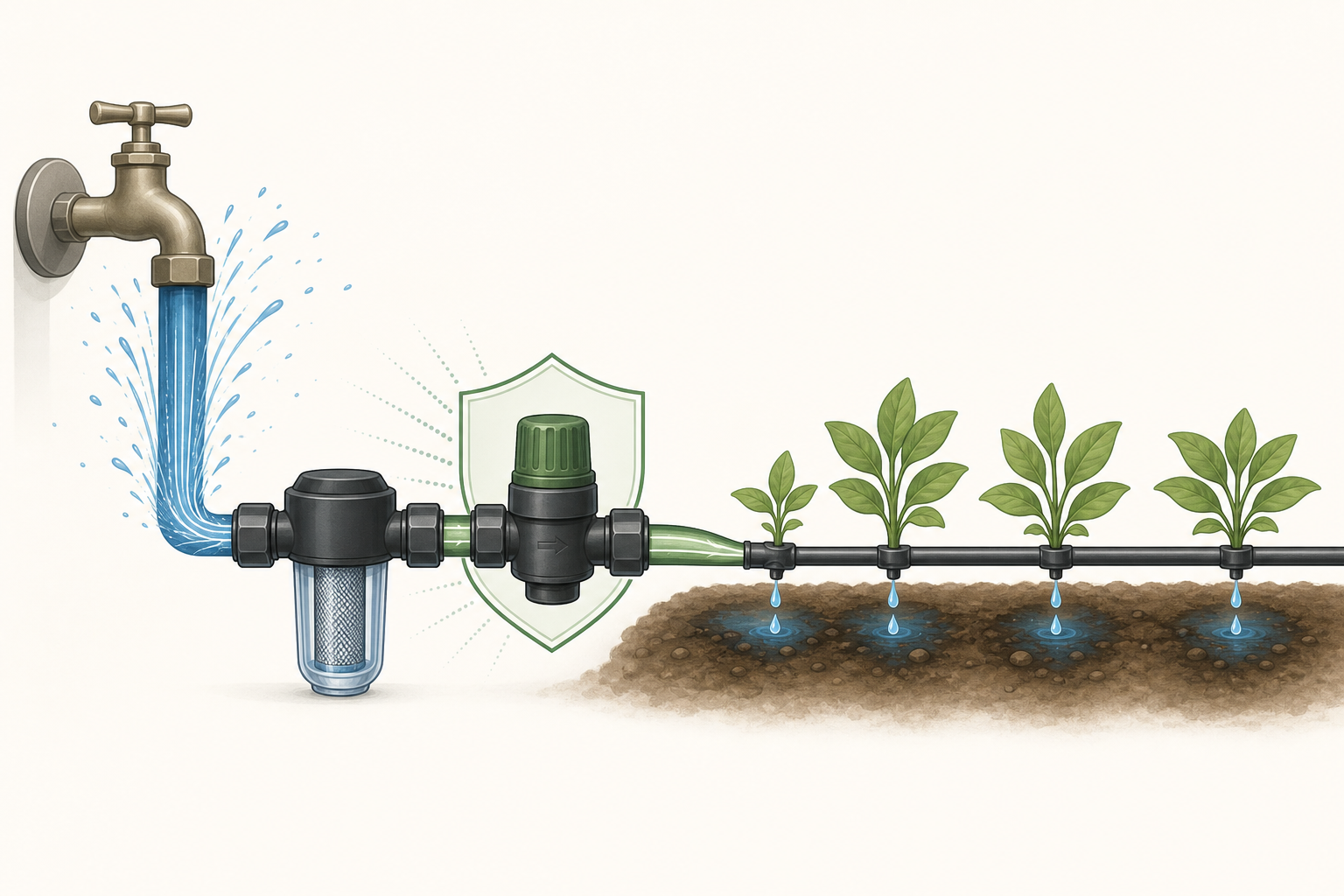
    Most faucet-fed drip systems need a pressure regulator when supply pressure exceeds the equipment’s recommended working pressure. For many garden emitter systems, 25 PSI is a useful starting point; drip tape often needs about 10–15 PSI. Choose the actual setting from your tubing and emitter specifications, then check that your zone’s flow matches the regulator.

    The number on the regulator is only part of the decision. A correctly labeled regulator can still perform poorly if too little water passes through it or the inlet pressure is insufficient.

    Do you need a pressure regulator for drip irrigation?

    A regulator reduces excessive incoming pressure to a suitable downstream level. It helps protect drip components from leaks, separated connections and excessive emitter flow. DIG describes its 25 PSI regulator as a way to bring household supply pressure into the working range of its drip equipment. See DIG’s specifications and installation guidance.

    You may already have suitable regulation in a drip-zone assembly. Check its outlet setting and flow range before adding another regulator. A timer alone does not establish that pressure regulation is included.

    If the source already delivers stable pressure within every downstream component’s permitted range, a separate regulator may be unnecessary. Verify the pressure during operation. A regulator cannot boost a weak supply; for that problem, start with Why Is My Drip Irrigation Pressure So Low?

    What PSI should you use: 10, 15, 25 or 30?

    Start with the exact equipment, especially whether you have thin-wall drip tape or thicker dripline. These starting points are not interchangeable product ratings.

    Your system Pressure to investigate What decides the setting
    Thin-wall drip tape Often 10–15 PSI The tape’s wall thickness, operating range and maximum pressure
    Garden tubing with separate drip emitters Often 25 PSI Emitter requirements and tubing/fitting limits
    Landscape dripline 25 or 30 PSI may suit the design The specific dripline’s pressure range and lateral-length tables
    Pressure-compensating dripline Use its specified design pressure Compensation range, line length, elevation and component limits

    Clemson Extension gives 30 PSI for typical landscape drip tubing and 10 PSI for garden drip tape. This explains why advice differs by system type; it does not make either number universal. Read Clemson’s filter and pressure-regulator guidance.

    Some products allow a much wider operating range. For example, Rain Bird lists 8.5–60 PSI for XPC pressure-compensating dripline. That is an operating range for that product, not a recommendation to run an entire mixed-component garden system at 60 PSI. See the XPC technical sheet.

    Pressure-compensating emitters do not replace system pressure protection. They stabilize emitter output within their specified range; tubing, fittings and other parts still have pressure limits.

    Check flow rate before buying a regulator

    Drip irrigation pressure regulators have a working flow range as well as a PSI rating. Calculate the demand of the zone that will actually run:

    For example, 12 emitters rated at 1 GPH total 12 GPH, or 0.2 GPM. That is below the 0.5 GPM minimum listed for Senninger’s PRL regulators. A regulator from that range would therefore be outside its published flow specification for this example, even with the right outlet PSI. Check the PRL flow specifications.

    Choose a model whose documented range includes your demand. For dripline, use its flow-per-length specification or calculate from emitter spacing. Include only outlets operating together. Our guide to how many drippers can go on one line explains the wider sizing checks.

    Before ordering, record the required outlet PSI, minimum and maximum GPM, permitted inlet pressure and connection type. Hose threads and tapered pipe threads are different; matching the nominal diameter alone is not enough.

    Where does the pressure regulator go?

    For a typical separate-component drip-zone assembly, the working order is control valve or timer → filter → regulator → drip tubing. Position backflow protection according to the approved device’s instructions and the requirements for your water connection; there is no single placement diagram that fits every device.

    DIG’s D46 instructions place the filter before the regulator and, for its illustrated automated faucet setup, the timer before the backflow device. Combined filter/regulator assemblies have their own instructions. Follow the manufacturer’s installation diagram.

    Many basic irrigation regulators must be downstream of shutoff valves because they are not designed for continuous supply pressure. Do not put one before a timer unless its documentation explicitly permits that arrangement. DripWorks explains the constant-pressure limitation.

    Shut off the water and release pressure before opening connections. Match the flow arrow to the direction of water travel, support the assembly and use the specified thread-sealing method. For the full watering setup, see how to automate a small drip irrigation system.

    How to test a drip irrigation pressure regulator

    Test while the zone is watering. A gauge attached to a closed outlet measures a no-flow condition, which may not show the regulated operating pressure.

    1. With the water off and pressure released, fit suitable gauge connections upstream and downstream of the regulator. Use a tee or test port that leaves water flowing to the emitters.
    2. Run the normal zone and allow the readings to stabilize.
    3. Check inlet pressure against the regulator’s requirements and compare downstream pressure with its specified output and tolerance.
    4. If the readings are suitable, compare water delivery near the beginning and end of the dripline.

    Senninger’s catalog describes this two-gauge check and specifies at least 5 PSI above the outlet setting for the models covered. A 25 PSI model with that requirement needs at least 30 PSI at its inlet while operating. Check your own model’s required margin. See Senninger’s testing and sizing guidance.

    Why is the pressure still wrong?

    What you observe Next check
    Outlet pressure stays too high Confirm the measurement is under flow, then check minimum flow, orientation and the model’s rating.
    The whole zone runs weakly Check inlet pressure under flow, the filter, valve opening and total demand before blaming the regulator.
    Only the far end is weak Check line length, restrictions, elevation and sizing; do not exceed component limits to compensate.
    Connections keep leaking Check operating pressure and fitting compatibility. A leak alone does not prove regulator failure.

    If pressure is suitable but connections still leak, use the drip connector repair guide. Replace a suspect regulator only after checking supply conditions, flow range and installation.

    Common questions

    Can I just turn the faucet down?

    A partly closed faucet restricts flow but does not maintain a preset downstream pressure as demand changes. Use an appropriately sized regulator when pressure reduction is needed. Clemson explains the limitations of using a valve this way.

    Is 15 PSI enough for drip irrigation?

    It can be, if the specific equipment operates correctly at that pressure throughout the zone. It is not automatically suitable for every dripline. Check minimum operating pressure and line-length guidance.

    Does a gravity-fed system need a regulator?

    Do not add a conventional regulator automatically to an already low-pressure supply. Verify available operating pressure and use equipment designed for those conditions. A regulator reduces pressure; it cannot create it.

    Should each zone have its own regulator?

    Size regulation for the zones and flows that operate together. Separate downstream regulators can accommodate different pressure requirements. A shared assembly needs to be suitable for its location and every intended operating combination.

    Before buying: identify your drip equipment, calculate the active zone’s flow and measure running pressure. Those three checks give you a much stronger basis for choosing a regulator than the PSI label alone.

    Not sure where to start? Open the Irrigation Troubleshooter.
  • Why Do My Drip Emitters Keep Clogging?

    Why Do My Drip Emitters Keep Clogging?

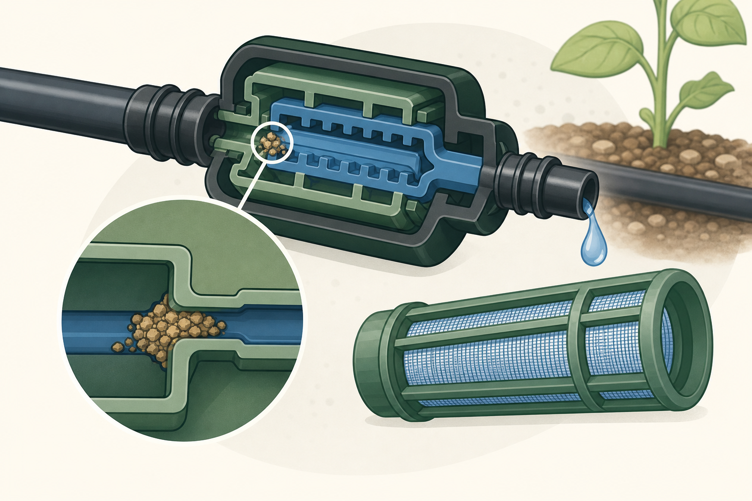
    Recurring emitter clogs are a symptom of contamination in the water or deposits forming inside the system. Replacing one blocked emitter may restore flow today, but the clog will return until the source is controlled.

    Three common types of clogging

    Physical particles

    Sand, soil, rust, and pipe debris can enter through the water source or during repairs. A correctly sized screen or disc filter is the main defense.

    Biological growth

    Algae, bacteria, and slime are more common with ponds, tanks, wells, or systems exposed to light and warm water. They can coat filters and small emitter passages.

    Mineral deposits

    Hard water can leave calcium or other precipitates. Iron in well water can also create deposits. The correct treatment depends on water chemistry; guessing with acids or chlorine can damage equipment or create a safety hazard.

    What to do first

    1. Inspect and clean the filter.
    2. Open line ends and flush until the water is clear.
    3. Check several emitters to see whether clogging affects one branch or the whole zone.
    4. Replace emitters that cannot be restored without changing their opening.

    Prevent the next clog

    • Use the filter mesh specified by the emitter manufacturer.
    • Choose a filter with enough flow capacity for the zone.
    • Keep end caps accessible and flush laterals periodically.
    • Prevent soil from being sucked into open emitters when the system drains.
    • Inspect filters more often when the source carries heavy sediment.

    Should you clean an emitter?

    Removable emitters can sometimes be rinsed according to their manufacturer’s instructions. Do not push a needle or drill bit into the outlet: it can permanently change the flow. With inexpensive sealed emitters, replacement is often more dependable.

    When water testing makes sense

    If mineral scale, orange deposits, slime, or rapid repeated clogging appears, test the source water and ask an irrigation professional or water-treatment specialist for a compatible treatment. Chemical injection requires correct equipment, backflow protection, dosing, and safety procedures.

    A clean filter plus regular flushing prevents most household drip problems. Persistent clogs point to a water-quality issue or unsuitable filtration—not bad luck.


    Related guides

    Not sure where to start? Open the Irrigation Troubleshooter.
  • Drip Irrigation Not Working at the End of the Line

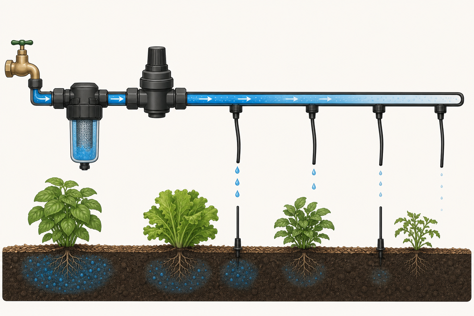
    When the first emitters work but the last plants stay dry, the system is losing too much pressure or flow before water reaches the end. The cause is usually excessive line length, too many emitters, a restriction, a leak, or an elevation change.

    Confirm the pattern

    Run the zone and compare the first, middle, and last emitters. If flow fades gradually, suspect hydraulic limits. If it stops suddenly, inspect that point for a kink, plugged fitting, closed valve, or blocked section.

    Flush the lateral

    Turn off the water, remove the end cap, then briefly run the zone into a bucket or safe drainage area. Sediment often collects at the end of a lateral. Refit the cap after the water runs clear.

    Check for hidden losses

    • Wet patches can indicate split tubing or a connector that has come loose.
    • Mulch or soil may hide a kink or crushed section.
    • A dirty filter can reduce flow to the entire zone.
    • Partially open valves and failing timers can restrict the supply.

    Count the total flow

    Add the rated flow of every emitter on the zone. The total must stay below what the water source, valve, regulator, filter, and tubing can supply together. Small 1/4-inch tubing should normally serve short branches, not act as the main supply for a long row.

    Consider slope and line layout

    Water pressure changes with elevation. On slopes or long runs, pressure-compensating emitters can improve uniformity, but they still need adequate inlet pressure. A looped layout or a larger supply line can also reduce differences between the start and end.

    The most reliable fixes

    1. Clean the filter and flush the line.
    2. Repair leaks and straighten damaged tubing.
    3. Reduce the number of emitters per lateral.
    4. Feed long laterals from a larger mainline.
    5. Split an oversized zone into two independently controlled zones.

    Do not solve an end-of-line problem by increasing pressure beyond the tubing or emitter rating. Better distribution and correct zone sizing are safer and more reliable.


    Related guides

    Not sure where to start? Open the Irrigation Troubleshooter.

  • Why Is My Drip Irrigation Pressure So Low?

    Why Is My Drip Irrigation Pressure So Low?

    Low pressure in a drip irrigation system usually shows up as weak flow, dry plants at the far end of a line, or emitters that stop dripping when another zone opens. The fastest way to solve it is to find where pressure or flow is being lost instead of replacing parts at random.

    Start with a quick diagnosis

    1. Run only the affected drip zone.
    2. Check whether every emitter is weak or only the last section.
    3. Inspect the filter and pressure regulator.
    4. Look for leaks, crushed tubing, sharp bends, and loose fittings.
    5. Open the end cap briefly and flush the line.

    If the whole zone has low pressure

    A clogged filter is the first thing to check. Turn off the water, remove the filter element, rinse it thoroughly, and reassemble it. A filter that is too small for the zone can also restrict flow even when it looks clean.

    Next, verify that the supply valve is fully open and that the timer or solenoid valve is opening correctly. If the zone shares water with another outlet, test it when no other irrigation or household demand is running.

    If only the end of the line is weak

    The zone may be asking for more flow than the source or tubing can deliver. Long runs, too many emitters, elevation changes, and small feeder tubing all increase pressure loss. Split a large zone into two shorter zones or use a larger mainline before adding more pressure.

    Check the regulator, not just the supply

    Most household drip equipment is designed for much lower pressure than a typical home water supply. Use a regulator that matches the tubing and emitter manufacturer’s specification. A regulator with the wrong pressure rating—or one operating below its required flow range—can cause poor performance.

    What not to do

    • Do not remove the regulator simply to force more water through the system.
    • Do not enlarge emitter openings with a pin; this changes their flow rate.
    • Do not keep adding emitters to a zone that is already uneven.

    Simple decision

    If cleaning the filter and flushing the line restores even flow, the problem was a restriction. If the beginning works but the end remains weak, shorten or divide the zone. If the entire line stays weak, test the supply, valve, regulator, and total zone demand.

    Safety note: shut off the water before opening filters, regulators, valves, or pressurized fittings. Follow the pressure limits printed by the component manufacturer.


    Related guides

    Not sure where to start? Open the Irrigation Troubleshooter.

  • Sprinkler Valve Won’t Shut Off: Causes and Safe Fixes

    A sprinkler zone that keeps running can waste a large amount of water. Shut off the irrigation supply if the valve will not close, then determine whether the controller is still energizing the solenoid or the valve is mechanically stuck open.

    Immediate action: stop the zone from the controller. If water continues, shut off the irrigation isolation valve. Do not disassemble a pressurized valve.

    Electrical or mechanical?

    Turn off power to the controller or disconnect the affected station wire. If the zone stops, investigate programming, controller output, or a wiring short. If it continues running with the solenoid de-energized, the valve is probably being held open by debris, diaphragm damage, incorrect assembly, or a manual bleed control.

    1. Check controller programs and start times

    Overlapping programs can make a zone appear stuck when it is actually receiving consecutive run commands. Review every program, start time, manual run, test cycle, and remote-control command.

    2. Close manual controls

    Make sure the solenoid and manual bleed screw are seated according to the valve instructions. Do not overtighten plastic parts. A partially open bleed screw intentionally bypasses the normal closing mechanism.

    3. Inspect the solenoid

    A jammed plunger or damaged seal can prevent correct operation. Shut off water and power, remove the solenoid as directed by the manufacturer, and check that the plunger moves freely. Replace it with the exact compatible part if damaged.

    4. Clean the diaphragm and pilot passages

    Mark the bonnet orientation, open the valve carefully, and keep springs and small components organized. Remove grit, scale, and plant material from the diaphragm seat and small control ports. Replace a torn, swollen, hardened, or permanently distorted diaphragm.

    5. Check pressure and flow direction

    Excessive pressure, reverse installation, or a missing internal component can prevent dependable closing. Confirm the flow arrow and operating-pressure range printed on the valve or documentation.

    When to replace the entire valve

    Replacement is usually the better choice when the body is cracked, sealing surfaces are damaged, threads are stripped, or the correct rebuild parts are unavailable. Confirm pipe size, connection type, voltage, pressure rating, and access space before purchasing.

    Final test

    Restore water slowly, check for external leaks, operate the zone electrically, and confirm that it closes fully after the controller stops. Observe the valve box for several minutes before backfilling or replacing the cover.


    Related guides

    Not sure where to start? Open the Irrigation Troubleshooter.

  • Low Water Pressure in a Sprinkler System: How to Find the Cause

    Weak sprinkler spray, heads that do not rise fully, and dry areas often point to a pressure or flow problem. The fastest diagnosis starts by determining whether the issue affects one head, one zone, or the entire system.

    First, define the scope

    • One sprinkler head: inspect the nozzle, filter, riser, and nearby pipe.
    • One complete zone: inspect the zone valve, lateral piping, and number of operating heads.
    • Every zone: check the main supply, backflow device, master valve, pump, and pressure regulator.

    1. Check for visible leaks

    Run the affected zone and look for pooling water, bubbling soil, unusually green strips, sunken areas, or a sprinkler head releasing water below ground. A broken lateral line can consume enough flow to weaken every head downstream.

    2. Clean clogged nozzles and filters

    Shut off the zone, remove the nozzle and internal filter, and rinse them with clean water. Replace damaged parts rather than enlarging nozzle openings. Verify that each nozzle matches the intended radius and precipitation rate.

    3. Confirm valve operation

    A valve that opens only partially restricts the entire zone. Check the flow-control position, solenoid installation, diaphragm condition, and pilot passages. Debris inside the valve can reduce flow even when the solenoid works normally.

    4. Look for excessive zone demand

    Adding heads or installing high-flow nozzles can exceed the available supply. Compare the total nozzle flow with the measured source flow. Splitting an overloaded zone or switching to lower-flow matched nozzles may be more reliable than increasing pressure.

    5. Measure pressure correctly

    Static pressure is measured with no water moving; dynamic pressure is measured while the zone operates. A strong static reading with a large drop during operation suggests restricted supply, excessive demand, or a leak. Use a gauge rated for the expected pressure and follow local backflow and plumbing requirements.

    Common causes across the whole system

    • Partially closed isolation or backflow valve
    • Blocked filter or pressure regulator
    • Municipal supply changes during peak demand
    • Weak pump performance or incorrect pressure switch settings
    • Mainline leak or failing master valve

    What to fix first

    Repair leaks and restrictions before changing nozzle sizes or controller run times. Pressure problems are hydraulic; increasing watering duration does not improve spray pattern or coverage.


    Related guides

    Not sure where to start? Open the Irrigation Troubleshooter.

  • Sprinkler Zone Not Turning On: Causes and Fixes

    When one sprinkler zone will not turn on, the cause is usually somewhere between the controller, field wiring, solenoid, valve, or water supply. This guide helps you isolate the fault in a logical order so you do not replace working parts.

    Safety first

    Turn off power to the irrigation controller before opening wiring compartments or disconnecting a solenoid. Shut off the irrigation water supply before removing valve components. If the system uses mains voltage or you are unsure about the wiring, call a qualified professional.

    Quick diagnosis: what the symptom usually means

    • The controller display is blank: check power, transformer, outlet, breaker, and controller fuse.
    • The controller runs but the zone is silent: suspect programming, a wiring fault, or a failed solenoid.
    • The valve clicks or hums but no water flows: check the water supply, flow control, diaphragm, or internal blockage.
    • The zone works when opened manually: the hydraulic side is probably functional; focus on the controller, wiring, and solenoid.
    • Several zones fail together: check the common wire, master valve, pump start circuit, rain sensor, or main supply.

    Tools that make diagnosis easier

    • Multimeter capable of measuring low-voltage AC and resistance
    • Small insulated screwdriver
    • Waterproof wire connectors
    • Replacement solenoid compatible with the valve
    • Clean towel, soft brush, and a container for small valve parts

    Step 1: confirm the controller is actually calling for the zone

    Start the affected zone manually from the controller. Confirm that the correct station number appears and that the remaining run time counts down. Review rain-delay settings, seasonal adjustment, sensor status, and start times. A programming issue can look exactly like a failed valve.

    If the controller reports a short circuit, overload, or station fault, stop repeated testing. Disconnect the zone wire and inspect the field wiring and solenoid before reconnecting it.

    Step 2: verify water supply and flow controls

    Make sure the irrigation isolation valve is open and that other zones can run normally. If every zone is dry, the problem is unlikely to be limited to one station. Systems supplied by a pump may also require a working pump-start relay or master valve.

    At the affected valve, check that any manual shutoff or flow-control stem is not fully closed. Do not force plastic controls; open them gradually and note their original position.

    Step 3: try the valve manually

    Most irrigation valves can be opened manually by slightly turning the solenoid or using a bleed screw. Follow the valve manufacturer’s method and avoid fully removing the solenoid while the water is on.

    • If the zone runs manually: the valve can pass water. Continue with electrical checks.
    • If the zone does not run manually: inspect the diaphragm, ports, flow control, and upstream supply.
    • If water leaks continuously afterward: close the supply and clean or rebuild the valve before continuing.

    Step 4: test controller output

    With the zone running, a typical residential controller sends approximately 24 volts AC between the station terminal and common terminal. Check the controller documentation for its specified output. A normal output at the controller but no voltage at the valve indicates a field-wiring problem. No output at the terminal may indicate programming, a damaged module, or controller failure.

    Step 5: inspect field wiring and connectors

    Look for loose, corroded, or non-waterproof splices inside the valve box. Gently pull each conductor to confirm it is secure. One solenoid lead normally connects to the station wire and the other to the shared common wire. A failed common splice can disable several valves at once.

    Repair damaged conductors with connectors rated for direct burial or wet locations. Ordinary indoor wire nuts can admit moisture and create intermittent faults.

    Step 6: test the solenoid

    With power off and at least one solenoid lead disconnected, measure resistance across the solenoid. Compare the reading with the manufacturer’s specification. An open circuit generally indicates a broken coil; a very low reading may indicate a shorted coil. Replace the solenoid when the measurement is clearly outside specification or when a known-good compatible solenoid operates the valve correctly.

    Step 7: clean or rebuild the valve

    If electrical operation is correct but water still does not flow, shut off the supply and open the valve body. Photograph the assembly before removing parts. Inspect the diaphragm for tears, deformation, debris, and blocked pilot passages. Clean components with water and a soft brush; avoid enlarging small ports with metal tools.

    Use the correct rebuild kit for the exact valve model. Mixing similar-looking diaphragms, springs, or bonnets can create unreliable operation.

    When replacement is the better option

    Replace the valve or controller component when the body is cracked, threads are damaged, repair parts are unavailable, or repeated repairs do not hold. Before buying, confirm pipe size, valve type, operating pressure, solenoid voltage, flow direction, and available space.

    Common mistakes to avoid

    • Replacing the valve before checking controller programming
    • Testing resistance while the circuit is energized
    • Using indoor connectors in a wet valve box
    • Opening a valve body without shutting off water
    • Buying a solenoid based only on appearance
    • Ignoring a shared common-wire problem when multiple zones fail

    A simple decision path

    If the valve opens manually, test the controller output, wiring, and solenoid. If the valve does not open manually, confirm supply pressure and inspect the valve internally. If several zones fail, investigate shared components before working on individual valves.

    Still not sure where the failure is?

    Record what happens during manual operation, which zones are affected, and any controller error. Those three details usually narrow the next test significantly.


    Related guides

    Not sure where to start? Open the Irrigation Troubleshooter.